Fiber is rarely where a project overspends. It is where a project discovers, on acceptance day, that a link is a few tenths of a dB over budget: traffic still passes, but the 40G module drops, or one cabinet starts losing packets every afternoon. What gets reworked then is not the cable - it is the ceiling, the tray and the wall that has already been closed.
This page does not repeat the selection logic (Cat6 versus OM4) already covered in structured cabling sourcing. It covers the three things a buyer can actually verify: how the link budget is calculated, which termination to buy, and which two test reports to require.
1. “It runs 10G” is an arithmetic table, not a promise
The application standard gives a maximum channel insertion loss. The buying job is to add up your own deductions and see what margin is left:
| Application | Fiber | Reach limit | Channel insertion loss limit |
|---|---|---|---|
| 1000BASE-SX | OM2 | 550 m | 3.6 dB |
| 10GBASE-SR | OM3 | 300 m | 2.6 dB |
| 10GBASE-SR | OM4 | 400 m | 2.9 dB |
| 40GBASE-SR4 (8-fiber MPO) | OM4 | 150 m | 1.5 dB |
Three deductions, all at the limit rather than the typical value:
- Cable attenuation: OM3/OM4 at 850 nm is 3.5 dB/km maximum under IEC 60793-2-10 (TIA-568.3-D calculates at 3.0 dB/km); 1300 nm is at least 1.5 dB/km
- Connectors: 0.75 dB per mated pair for standard grade, the TIA-568.3-D limit; 0.30 dB for reference grade on multimode
- Splices: 0.3 dB each as the standard limit, with 0.15 dB common on single-mode fusion splicing
Worked example: a 400 m OM4 backbone in an office building, one patch panel pair at each end, two splice points in the middle, running 10GBASE-SR.
| Deduction | Value |
|---|---|
| Cable (0.4 km x 3.5 dB/km) | 1.40 dB |
| Connectors (2 pairs x 0.75) | 1.50 dB |
| Splices (2 x 0.3) | 0.60 dB |
| Total | 3.50 dB |
| Application limit | 2.9 dB - 0.60 dB over, fails |
The same link with pre-terminated ends (one pair at each end, no splices) totals 2.15 dB with 0.75 dB of margin. That is why backbones move to pre-termination: what you save is not labour, it is 1.35 dB.
When the whole low-voltage package is bought together, fiber is usually the last leg of the backbone and the hardest to redo; the package scope and interface split is set out in hotel ELV system integration. Below the backbone sits the access layer, where port density and uplink budgets are covered in PoE switch sourcing.
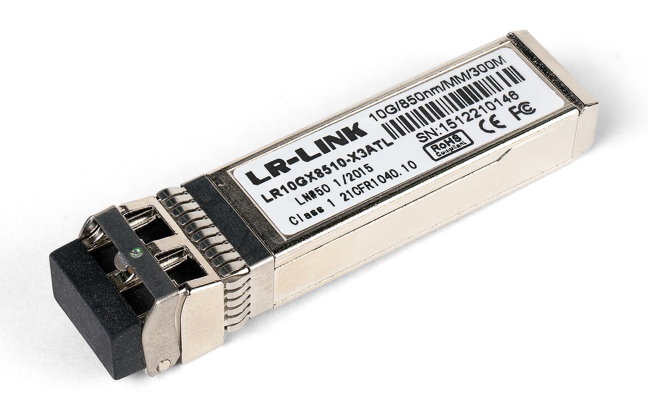
2. Three termination methods: who carries the 0.6 dB
| Method | Loss per point | Site work | Rework | Fits |
|---|---|---|---|---|
| Fusion splice with pigtails | 0.3 dB limit | Splicer, splice tray, construction record | Medium (re-splice) | Backbone, outdoor, single-mode long reach |
| Pre-terminated MPO | 0.75 dB per pair (standard grade), low-loss grade optional | Plug and test polarity | Low (swap module) | Comms room to floor, 40G/100G |
| Field-assembled connector | Depends on the installer, batch variation | No splicer needed | High (re-terminate) | Temporary links, a few extra points |
3. Fix polarity before the quotation, not on commissioning day
Duplex links use one of two arrangements (TIA-568.3-D Annex C): consecutive-fiber positioning (A-B at one end, B-A at the other) or reverse-pair positioning (same orientation at both ends, 2,1,4,3 at one end). Array (MPO) links use three methods, and they are not interoperable:
| Method | Trunk type | 12-fiber mapping | Typical use |
|---|---|---|---|
| A | Type A, key-up to key-down | P1 to P1 | Most common, with A-to-B and A-to-A jumpers |
| B | Type B, key-up to key-up | P1 to P12 | Parallel links when 10G migrates to 40G/100G |
| C | Type C, pair-wise flipped | P1 to P2 | Duplex backbones with standard A-to-B jumpers |
Later revisions of TIA-568.3-D add Methods U1 and U2, which support multiple duplex signals only and no array links. The buying action is simple: put the method letter and jumper types in the BOM, never just “MPO trunk”. A polarity error will not show up as excess loss - it shows up as every link reversed on the day the network is switched on.
4. End faces: blue and green do not mate
| Item | UPC | APC |
|---|---|---|
| End face | Flat (slightly domed) | 8 degrees angled |
| Return loss floor | 50 dB or better | 60 dB or better |
| Colour | Blue | Green |
| Fiber | Single-mode and multimode | Single-mode |
| Mating | Mated with APC the insertion loss reaches 3 dB or more and both ferrules are damaged | - |
Cleaning and inspection follow IEC 61300-3-35:2022 (third edition): zone A (core) and zone B (cladding) plus the whole contact area, up to 250 um diameter on cylindrical ferrules. That edition removed the zone C and D requirements and states explicitly that visual inspection does not replace attenuation and return loss measurement. In practice the most expensive mistake is an ODF ordered with APC adapters and patch cords shipped UPC - discovered only when the goods arrive.
5. Two reports: Tier 1 decides, Tier 2 locates
TIA-568.3-D Annex E splits field testing into two tiers:
- Tier 1 (OLTS): loss, length and polarity - this is the pass/fail record; field methods follow IEC 61280-4-1 for multimode and IEC 61280-4-2 for single-mode
- Tier 2 (OTDR): the event trace, showing which connector, splice or bend carries the loss
The OTDR has to be bidirectional. Measured from one end only, two connectors with different backscatter produce a negative-loss “gainer” event that reads better than the link really is. A proper report therefore contains traces from both directions plus the event table, not a single screenshot.
6. At 40G the margin is a few tenths of a dB: MPO grade decides
On the same 150 m OM4 run for 40GBASE-SR4 (8-fiber MPO uplink), the limit is only 1.5 dB:
| Component | Standard-grade MPO | Low-loss MPO (0.35 dB per pair) |
|---|---|---|
| Cable (0.15 km x 3.5) | 0.53 dB | 0.53 dB |
| 2 connector pairs | 1.50 dB | 0.70 dB |
| Total | 2.02 dB - fails | 1.23 dB - passes |
The difference is neither cable nor distance, only whether the quotation says “low-loss grade”. On links like this, paying slightly more at quotation stage is much cheaper than opening the ceiling at acceptance.
7. A 500-room hotel backbone: count the fibers first
| System | Points | Fibers (1 per point) | With 20% spare |
|---|---|---|---|
| Cameras | 120 | 120 | 144 |
| Access points | 214 | 214 | 257 |
| Access control points | 60 | 60 | 72 |
| Total | 394 | 394 | 473 |
473 fibers is about 20 positions on 24-fiber ODF panels; three risers at two 24-fiber cables each comes to 144 backbone fibers. Fiber count, ODF positions and patch cord quantities are all arithmetic - do not accept “as per experience”. On the cabinet side, U-space and dressing space are broken down in ELV package delivery and handover.
8. Ten lines for the RFQ
- Fiber type (OM3 / OM4 / OS2), core count and number of runs
- Cable construction: tight or loose buffer, indoor or outdoor, flame class (CPR class where required)
- Termination method (fusion, pre-terminated MPO, field-assembled) and who performs the splicing
- Polarity method and jumper types, with the method letter written out
- Connector type and grade (LC/SC, UPC/APC, standard or reference grade)
- MPO grade (standard or low-loss) and fiber count (8/12/24)
- ODF specification: 24-fiber positions, adapter type, splice tray included or not
- Test scope: whether Tier 1 includes length and polarity, and whether bidirectional Tier 2 traces are supplied
- Delivery documents: attenuation report, polarity table, reel-to-link cross reference
- Spare ratio (patch cords, adapters, pigtails), warranty and the non-conformance clause
9. Five goods-in checks and three site acceptance items
Goods-in: (1) microscope-inspect the first and last connector of each reel; (2) measure insertion loss and return loss on three random patch cords against their marked grade; (3) metre marks continuous along the jacket with no joints; (4) ODF adapter type matches the BOM - this is the step that catches APC/UPC mix-ups; (5) polarity and labelling match the manufacturer’s polarity table.
On site: (1) Tier 1 on 100% of links, with anything over budget failing and no sampling; (2) Tier 2 bidirectional traces on a 10% sample, with no unexplained spikes in the event table; (3) a link register (link ID, both end ports, length, measured loss) matching the cabinet labels one for one.
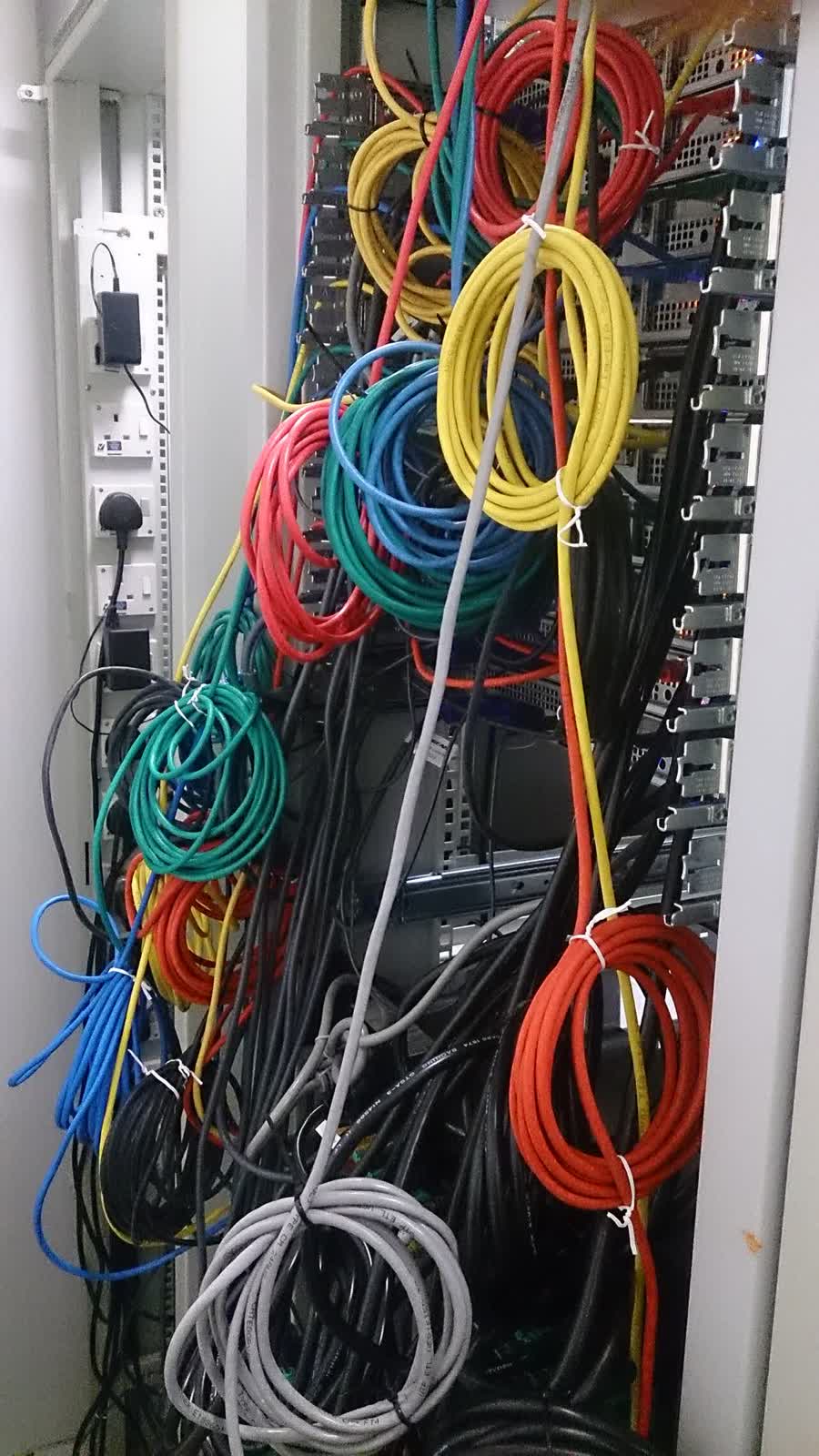
The link register earns its place in the contract because it decides whether, three years later, anyone can tell which port goes to which floor when a 40G link is added. Without it, a fiber backbone is a pile of patch cords that all look the same. The point counts behind those links are in CCTV camera sourcing and the routing side is in cable tray and containment.
10. Six traps
- Budgeting with typical values: 3.0 dB/km cable and 0.3 dB connectors make a beautiful table that fails on the day acceptance applies the limits
- Polarity only on the drawing: no method letter in the BOM or jumper list, so every contractor interprets it differently
- APC and UPC mixed: a green connector into a blue adapter starts at 3 dB of insertion loss
- One-direction OTDR screenshots: gainers stay invisible and nobody knows which connector carries the loss
- MPO without a grade: the two quotations differ in connector grade and nobody can see it at bid evaluation
- Fiber count sized to today: three years later one more 40G run finds no spare fiber
What to send us
The verifiable part of fiber comes down to four numbers: application limit, cable attenuation, connector and splice deductions, measured loss. Put those four into the RFQ and the acceptance clause, and the rest is who produces the reports and whether they can be read. Send a drawing or BOM and we will return the loss calculation and test scope in writing within 48 hours; the free RFQ template lines up the fields first.
For the whole package - cameras, access control, wireless, IPTV and backbone in one procurement chain - see hotel ELV system integration, or contact us with the project scope.