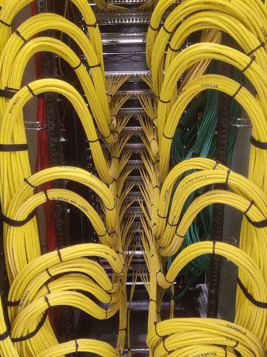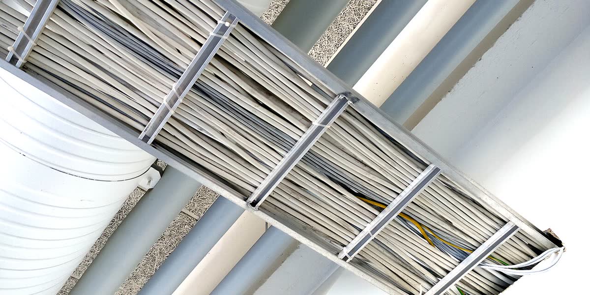
The part of a low-voltage package that goes wrong is usually not the camera. It is the cable that will not go in.
On the drawing, the riser is a single diagonal line; on site, 600 Cat6 cables have to go into a 300 mm wide tray. The quotation says “tray, 300 m” and tells you nothing about width, height or sheet thickness. On acceptance day it turns out there is no bonding jumper and the fire classification came from a component test. All three have the same shape: they are decided before the cable is pulled, and once the ceilings and shafts are closed they cost the ceiling and the shaft to fix.
This article is not a product catalogue. It gives four numbers a buyer can check - fill rate, load, separation, coating - plus the two acceptance actions: fire and earthing.
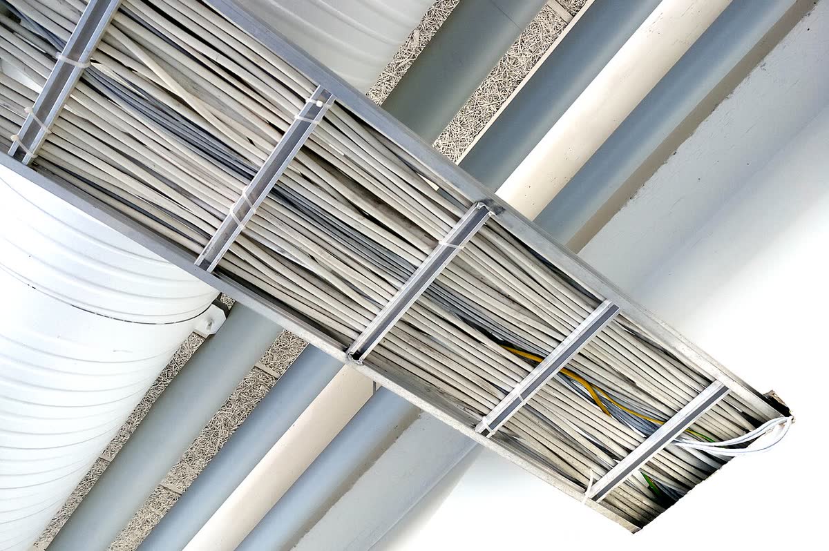
Photo: Santeri Viinamäki, CC BY-SA 4.0, via Wikimedia Commons.
1. Tray, trunking and conduit are three products under three standards
Mixing the names is the most common mistake, and the result is a quotation in which three products share one set of technical clauses.
| Category | Typical form | Governing standard | Main duty | Unit of pricing |
|---|---|---|---|---|
| Cable tray (tray / ladder) | Ladder, solid-bottom, perforated, wire mesh | IEC 61537 (third edition 2023 replaced the 2006 second edition; adds SWL test types and an annex on tray used as a protective conductor) | Horizontal backbone, comms room, risers | Per metre (width x height x sheet thickness) + fittings per piece |
| Trunking | Closed wall or ceiling run with a lid | EN 50085-1 / -2-1 (slotted trunking inside enclosures falls under -2-3); IEC equivalent IEC 61084 series (EN IEC 61084-2-1:2024) | Final runs to workstations, corridor wall runs | Per metre + fittings |
| Conduit | Rigid or flexible, metal or plastic | IEC 61386 series | Single-point final drops, surface and concealed | Per metre + saddles |
One-line memory: tray carries the big bundle, trunking carries the banked branches, conduit carries the last cable. A quotation has to separate these three, otherwise you cannot tell whether “300 m of tray” and “200 m of trunking” on the same BOQ are the same goods priced twice.
2. Choose the form first: five tray types for five situations
| Type | Construction | Strength | Do not use it for |
|---|---|---|---|
| Ladder | Two side rails plus rungs | Best heat removal, long spans, easy single-layer dressing | Areas where small parts can fall through |
| Solid bottom | Closed base plate | Keeps dust out, holds small items, better screening | Dense high-current runs that need to shed heat |
| Perforated | Punched base | Balance of heat removal and fixing, the general-purpose choice | Dusty workshops - the holes fill up |
| Wire mesh | Welded steel wire | Light, flexible on site, well ventilated | Heavy backbones, or anywhere screening matters |
| Wide-span / heavy duty | Reinforced rails plus intermediate supports | Long spans with fewer brackets | Retrofits with limited headroom |
The perforated metal tray dominates low-voltage backbones because it satisfies three things at once - heat, fixing, and one key condition: under EN 50174-2 the “perforated metal” row gives a far smaller separation than open wiring with no divider (see section 6).
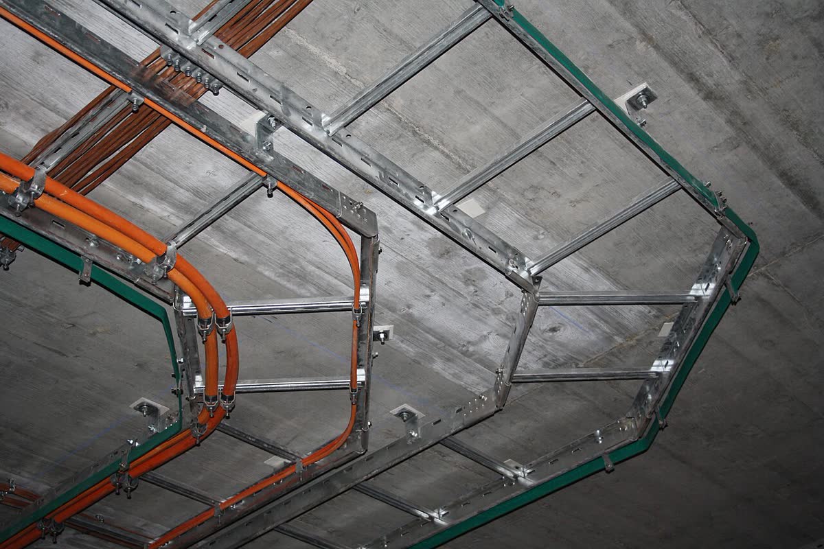
Photo: Leotard, CC0, via Wikimedia Commons.
If you want the shape of the whole package first - where the backbone tray, the comms room cabinets and the point drops sit, and who owns each - our hotel low-voltage systems integration page breaks the structure down the same way.
3. Fill rate: convert outside diameter to cross-section, then pick width and height
The most common purchasing error is negotiating tray by cable count instead of by cross-section. The calculation is three steps: look up the cable outside diameter, work out the single-cable cross-section, divide by the tray’s internal cross-section.
Take 600 Cat6 cables at 6.0 mm outside diameter (28.3 mm2 each, 16,965 mm2 in total):
| Tray internal size | Internal area | Fill with 600 cables | Estimated layers (300/400 wide) | Verdict |
|---|---|---|---|---|
| 300x60 | 18,000 mm2 | 94.2% | 12 layers / needs 72 mm height | Not usable, and too shallow |
| 300x100 | 30,000 mm2 | 56.5% | 12 layers / needs 72 mm height | Over the 50% ceiling for control/signal cable |
| 400x60 | 24,000 mm2 | 70.7% | 10 layers / needs 60 mm height | High, no room to grow |
| 400x100 | 40,000 mm2 | 42.4% | 10 layers / needs 60 mm height | Usable |
| 500x100 | 50,000 mm2 | 33.9% | 8 layers / needs 48 mm height | Headroom for later expansion |
Two rules have to be used together:
- Fill ceiling: NEC 392.22 gives 50% for a tray carrying control and signal cable only (40% for solid-bottom trays). Power cable has its own table of permitted fill area by tray width (for example 7 in2 at 6 in wide, 14 in2 at 12 in wide) - do not copy the 40% conduit rule across to tray.
- Expansion headroom: work back from 70% for the minimum cross-section. At 6.0 mm outside diameter that is at least 24,235 mm2; at 6.5 mm outside diameter (a thicker LSZH sheath) it becomes 28,443 mm2 - the same “600 cables”, a 0.5 mm difference in diameter, and nearly a fifth more cross-section needed. That is why the supplier has to calculate from your cable datasheet, not from experience.
4. Load and span: SWL is a number “at your span”
A tray is a structural component, not sheet metal. The core of IEC 61537 is the SWL (safe working load) test: at the rated SWL the lateral deflection must stay within 1/100 of the span and the transverse deflection within 1/20 of the nominal width, and at 1.7x SWL the assembly must not collapse. In other words, a supplier who quotes “XX kg/m” without a span has quoted nothing.
The weight arithmetic (Cat6 at 45 kg/km, confirmed against the datasheet):
| Item | Value |
|---|---|
| Weight of one Cat6 cable | 45 g/m |
| 600 cables | 27.0 kg/m |
| Plus tray self-weight 3.5-5 kg/m | 30.5-32.0 kg/m |
| Load per bracket at 1.5 m span | 46-48 kg |
| Load per bracket at 3.0 m span | 92-96 kg |
So the RFQ asks three things: what SWL applies at the span on your drawing (1.5 m / 2 m / 3 m), what hanger rod specification is used, and how additional support at bends and tees is counted. Going from a 1.5 m to a 3 m span halves the bracket count and cuts cost, but the tray specification has to be upgraded with it - this is the item a “cheaper option” quietly changes.
5. Material and corrosion protection: coating thickness can be measured
Nine out of ten low-voltage trays are steel; the difference is the corrosion system. Hot-dip galvanising is banded by steel thickness under EN ISO 1461:
| Steel thickness | Local minimum coating | Average minimum coating |
|---|---|---|
| Over 6 mm | 70 um | 85 um |
| Over 3 mm to 6 mm | 55 um | 70 um |
| 1.5 mm to 3 mm | 45 um | 55 um |
| Under 1.5 mm | 35 um | 45 um |
Three comparisons tell you whether a quotation matches:
- Hot-dip versus pre-galvanised (such as Z275, 275 g/m2 both sides): pre-galvanised is cheaper and leaves cut edges unprotected; it is adequate in dry indoor space. Outdoors, in basements and at the coast you need hot-dip, or 304/316L.
- Powder coating: it looks good but only changes the appearance; cut edges and scratches still rust. State whether the substrate is galvanised before coating.
- Non-metallic: FRP is used for severe corrosion, substations and chemical plants. It is non-magnetic and non-conductive, and at the same time it loses the property that makes a metal tray an equipotential body - the earthing design has to be done separately.
At goods-in, check three things: coating thickness gauge readings against the table above, sheet thickness with a caliper rather than the nominal figure, and whether perforation and welds are continuous. The way tray gets “lightened” is very plain - 1.5 mm sheet becomes 1.2 mm and looks identical.
6. Power and data in one tray: calculate to EN 50174-2, do not just add a divider
This is the section most easily fudged verbally. The EN 50174-2 method is minimum separation A = S x P: S comes from the screening class of the information cable and the form of the tray, P from how many power circuits run alongside.
S (mm, the two common bands):
| Information cable screening class | No divider / open wiring | Open metal tray | Perforated metal trunking | Solid metal trunking |
|---|---|---|---|---|
| b (ordinary U/UTP Cat6) | 100 | 75 | 50 | 0 |
| c (screened Cat6/Cat6A) | 50 | 38 | 25 | 0 |
| d (Cat7/7A class screening) | 10 | 8 | 5 | 0 |
| a (unscreened, low performance) | 300 | 225 | 150 | 0 |
P (counted in 20 A / 230 V single-phase circuits, a three-phase circuit counts as 3):
| Power circuits | 1-3 | 4-6 | 7-9 | 10-12 | 13-15 | 16-30 | 31-45 | 46-60 | 61-75 | over 75 |
|---|---|---|---|---|---|---|---|---|---|---|
| P | 0.2 | 0.4 | 0.6 | 0.8 | 1.0 | 2 | 3 | 4 | 5 | 6 |
Worked example: U/UTP Cat6 in perforated metal trunking beside eight power circuits gives 50 x 0.6 = 30 mm; the same cable in open wiring with no divider gives 100 x 0.6 = 60 mm. The 0 mm for solid metal trunking has a precondition: the screening performance must equal 1.5 mm steel wall thickness, which stainless steel and aluminium do not meet; perforated trunking also requires the top of the cable to sit at least 10 mm below the top of the divider.
The purchasing action is one sentence: write the separation and the tray form into the drawing and the acceptance sheet, and require the supplier to state whether a metal divider is included and how thick it is. Without that sentence, site practice is one cable tie around both bundles, and the test fails later.
7. Fire: accept a system report, not the words “fire-rated tray”
The dividing line in fire performance is whether a component burns versus whether the circuit keeps working. In low-voltage work the thing that actually has to survive is the second one - the control circuits for fire alarm, escape lighting, fire-fighting lifts and mechanical smoke extraction.
DIN 4102-12 tests the whole system: tray, supports, hangers, fixings and cable go into the furnace together (furnace temperatures above 1,000 C), and circuit integrity is classified E30 / E60 / E90. The report fixes the permitted support spacing and cable load (commonly the 1.2 m, 10 kg/m band). The usual engineering mapping is: alarm, escape lighting and fire-fighting lifts at 30 minutes (E30); automatic extinguishing and mechanical smoke extraction at 90 minutes (E90) - subject to the local code and the design statement.
So the RFQ asks for three documents: the system test report (including permitted spacing and load), the cable type used in the test, and the installation instructions. Acceptance measures the support spacing as built - widen 1.2 m to 1.5 m and that report no longer covers your installation. Separately, sealing where the tray passes through walls and floors is done to EN 1366-3, which is a different matter from the tray’s fire classification; one does not substitute for the other.
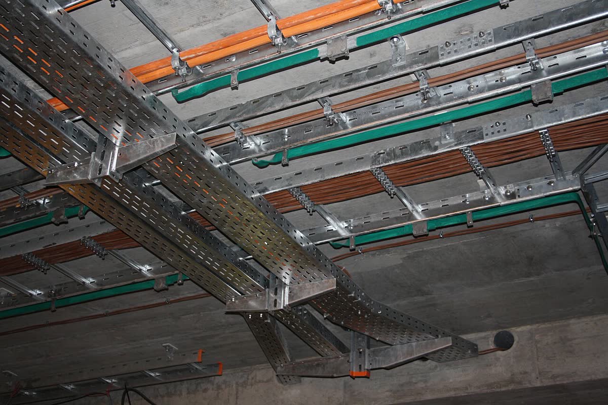
Photo: Leotard, CC0, via Wikimedia Commons.
8. Earthing and equipotential bonding: put the jumper count in the quotation
A metal tray is an exposed conductive part and has to be included in equipotential bonding. The verifiable criterion is the IEC 61537 electrical continuity test: at 25 A, joint transition resistance no more than 50 mOhm, and no more than 5 mOhm/m over a 500 mm length with no joint. On site that becomes three actions:
- Connect each section with a dedicated bonding jumper or braid - do not rely on the bolted splice alone.
- Connect the end of the run reliably to PE, and repeat the bonding per floor in risers.
- Put the jumper count into the quotation - “two per section” or “one per 6 m” changes both the price and the acceptance result.
If the design wants to use the tray body as a protective conductor, IEC 61537:2023 added an annex for exactly that, but the cross-section and connection conditions have to be checked against the annex - do not assume that “metal means it can be the PE”.
9. Ten lines in the RFQ, and quotations become comparable
| # | Required line | Why |
|---|---|---|
| 1 | Category (tray / trunking / conduit) plus form (ladder / solid / perforated / mesh) | Decides which standard applies |
| 2 | Width x height (internal clear size) | Fill is calculated on the internal cross-section |
| 3 | Sheet thickness | The item most often lightened |
| 4 | Material and corrosion system (hot-dip / pre-galvanised / 304 / 316L / FRP plus coating band) | Decides service life |
| 5 | Span and SWL (state 1.5 m / 2 m / 3 m) | SWL without a span means nothing |
| 6 | Fitting schedule (bends, tees, reducers, brackets, hangers, bonding jumpers, dividers) | Fittings are often 30-40% of the total |
| 7 | Whether a metal divider is needed, and its thickness | Decides the power/data separation |
| 8 | Fire classification (does it need a DIN 4102-12 system report, E30/E90) | Decides whether certified documents are required |
| 9 | Surface treatment and cut-edge protection (how site cuts are treated) | Decides where the rust starts |
| 10 | Packing and marking (length and location reference on every section) | Decides how long site spends finding material |
10. Six traps
- Negotiating tray by cable count: no outside diameter, no cross-section, and the cables are forced in on site.
- Pricing by the tonne: width, sheet thickness and coating are all averaged away, and acceptance has nothing to check against.
- SWL without a span: the number in the report belongs to somebody else’s bracket spacing.
- Adding a divider instead of calculating separation: divider thickness and material change the S value by a whole band.
- Accepting a component report for fire: a tray that will not burn is not a circuit that keeps working.
- Leaving bonding jumpers off the schedule: the cheapest quotation is often the one that dropped this line.
If the project in front of you is a hotel, a campus or a factory low-voltage package, the tray section usually ships with the structured cabling and the rack integration and FAT handover as the same consignment and the same customs entry - read the three BOQs together and the duplicate pricing you remove is usually worth more than the unit price you negotiate.
If you want a drawing checked for tray cross-section, span and separation, or an RFQ list you can send straight to a factory, send the drawing and the point schedule over: we return an item-by-item review within 48 hours, marking which items must change and which can be optimised. The entry point is contact us, or fill in the parameters with the RFQ template.