Guest WiFi is the #1 source of hotel complaints that never make it into a review card — “the internet was slow,” “I couldn’t connect,” “the TV buffered all night.” The difference between a hotel network guests praise and one they silently endure is rarely the internet provider. It is the device-level design: which access points, how many, where they go, how they get power, and how the whole thing is managed.
For how this fits the other building systems, see our overview of ELV systems sourced from China.
This article walks through the actual network design of a 500-room hotel in Central Africa — the same 18-story project covered in our floor-by-floor ELV design case study. This time we go one level deeper: the WiFi access point plan, the switching architecture, and the video storage that sits behind the surveillance system.
What are the three types of access points and their jobs?
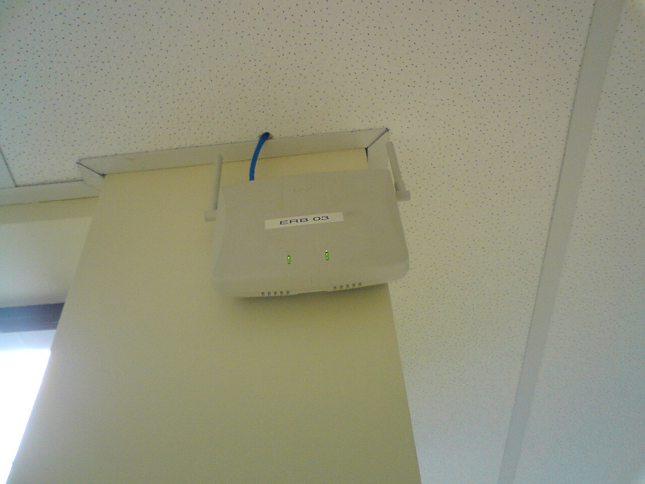
The WiFi design for this hotel is built on Wi-Fi 6 access points in three physical form factors, each chosen for a different part of the building:
| AP type | Where it goes | Design capacity |
|---|---|---|
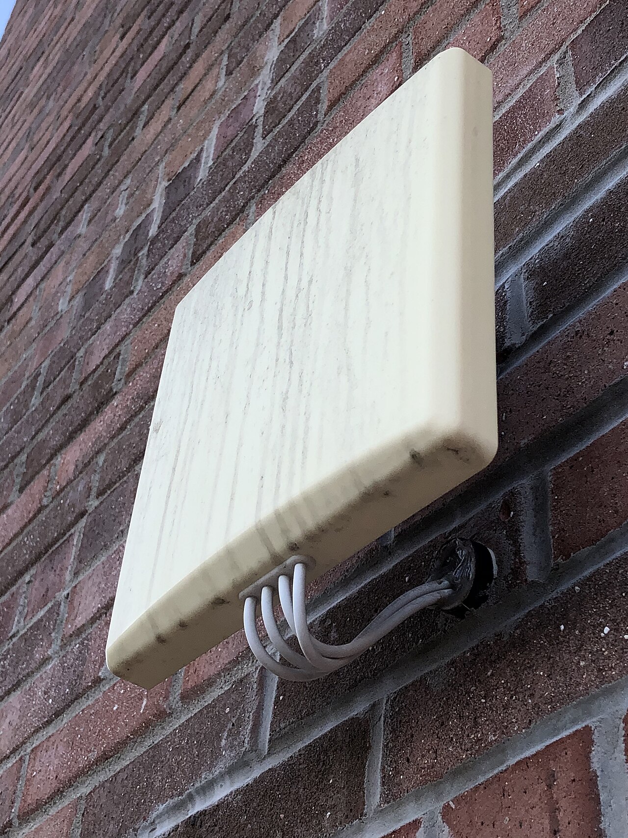
| Wall-plate AP | Guest rooms, suites | Up to 60 concurrent users, dual-band, 4 streams (~1.8 Gbps) |
| Ceiling AP (high-density) | Corridors, lobby, meeting rooms | Up to 300 users, triple-band, 6 streams (~3.3 Gbps) |
| Outdoor AP | Terrace, pool area, roof | Up to 100 users, dual-band, internal/external antennas |
The selection logic matters more than the model numbers:
- Wall-plate APs go in rooms where guests are the users — one per room or per room pair, mounted where the TV and desk are.
- Ceiling APs carry the load in open, high-density spaces: corridors (where every room’s device fights for signal), lobby, restaurants, and the 9th-floor leisure zone.
- Outdoor APs handle the terrace, pool and roof areas where a ceiling mount is impossible.
A common mistake is buying one “good enough” AP model for the whole building. Here, capacity is matched to the space: a triple-band ceiling unit for the 300-user event floor, a modest wall-plate unit for a guest room. You pay for density only where density exists.
Where did the 214 access points go in the per-floor plan?
The project’s AP quantity table is the most useful part of this design, because it shows how room type changes network demand. Here is the actual placement (wall-plate + ceiling APs per floor):
| Floor / area | Wall-plate APs | Ceiling APs |
|---|---|---|
| Basement | 1 | 7 |
| Ground floor | 17 | 1 |
| Mezzanine | 7 | 16 |
| 1st–2nd floor (guest rooms) | 56 | 8 |
| 3rd–6th floor (guest rooms) | 88 | 16 |
| 7th floor suites | 22 | 1 |
| 8th floor suites | 20 | 1 |
| 9th terrace (leisure) | 15 | 1 |
| 10th–11th penthouses | 24 | 14 |
| 12th floor | 20 | 3 |
| 13th floor offices | 18 | 6 |
| 14th roof | 14 | 1 |
| Rotating restaurant | 10 | 1 |
| Total | 214 | 169 |
Read the table like a network engineer:
- Guest room floors (1–6) are wall-plate heavy: roughly 10–14 rooms per floor, each with a dedicated AP. Transient guests don’t roam much, so per-room coverage beats long-range ceiling units.
- The penthouses and mezzanine flip the ratio — more ceiling APs relative to wall plates, because suites have bigger living areas and open layouts where a single wall unit won’t cover.
- 13th floor offices get a high ceiling-AP ratio (6 ceiling units for 18 wall plates) because office users move between desks and meeting rooms — roaming matters.
- The rotating restaurant on the roof gets 10 dedicated APs: a moving, crowded, glass-walled venue is one of the hardest WiFi environments in the building.
How do 2.4G and 5G signal diagrams help before installation?
Every floor of this project has a signal simulation diagram for both 2.4 GHz and 5 GHz before a single AP is mounted. This is a step most hotel WiFi projects skip, and it is exactly where the quality is won.
The simulations answer three questions:
- Coverage holes — where signal drops below the usable threshold (especially corridors and bathroom zones behind thick walls)
- Overlap — where neighboring APs on the same channel interfere with each other, which matters more in 5 GHz than 2.4 GHz
- Capacity hot spots — where the AP count is right but the density of clients will exceed what the radios can serve (breakfast rush in the ground-floor restaurant, check-in crowd in the lobby)
The diagrams also show the weak-current rooms (floor telecom closets) that anchor the cabling: every AP has a cable path back to a closet, and the simulation is only useful if the AP positions respect where cabling can actually run. Design the coverage on paper, then confirm the AP count in the bill of materials — never the other way around.
What are the core, aggregation, and access layers of the network backbone?
Behind the APs sits a three-tier switching architecture:
- Core switch — a chassis switch with redundant power modules and dual main processing units (MPU), so a power supply or control-card failure does not take down the network. The basement control room hosts the core, with the fiber backbone rising through the floors.
- Aggregation switches — 48-port units with 10G uplinks that collect traffic from groups of floors.
- Access switches — cloud-managed PoE switches at each weak-current room that power and connect the APs and cameras on their floor.
The redundancy design is deliberate for a market where an outage means guests checking out: no single power supply, no single control card, no single uplink between floors. The fiber backbone between floors means a failed link on one floor cannot take out the floor above it.
How does PoE power access points and cameras over one cable?
Power over Ethernet is where the network meets the physical building. This design uses the full modern PoE range:
| PoE class | Power per port | Typical device |
|---|---|---|
| 802.3af | 15 W | Basic IP phones, low-end APs |
| 802.3at | 30 W | Standard Wi-Fi 6 APs, most cameras |
| 802.3bt | up to 90 W | High-density triple-band APs, PTZ cameras |
Three PoE features in this design are worth insisting on for any hotel:
- PoE watchdog — the switch detects a camera or AP that has hung and automatically power-cycles that single port. In a hotel, this is the difference between “one camera offline until a technician visits” and “the system heals itself in minutes.”
- Loop protection — a misconnected cable that creates a network loop can bring down a floor; the switch detects and blocks it instead.
- Perpetual PoE — devices stay powered during switch firmware upgrades, so a routine maintenance window does not reboot the entire camera system at 3 AM.
How does cloud management unify the whole property in one dashboard?
The project’s network gear is cloud-managed — every switch, router, AP and camera registers to a cloud platform, and the hotel operator (or the sourcing partner) configures and monitors the whole property from one dashboard.
The practical value for a remote hotel in Central Africa is hard to overstate:
- Zero on-site config expertise required. The platform’s guided configuration activates the full security-and-network stack in roughly five minutes per device group, instead of configuring each device through a command line.
- Remote troubleshooting down to the minute. When a guest reports a dead camera or a weak signal zone, the operator can locate the device, view a live snapshot, and restart the camera or its switch port remotely — no truck roll across town.
- One-click restart per port. The most common fix in hotel networking (“just reboot it”) becomes a remote action tied to the exact device.
For a property where the nearest network engineer may be a plane ride away, cloud management is not a convenience — it is the maintenance plan.
Where does the CCTV footage live in video storage?
The surveillance side of this network needs serious storage, and the design specifies an embedded video storage (EVS) system rather than a pile of NVRs:
- Capacity: 24/36/48-bay models, supporting 20 TB enterprise drives — the 48-bay unit in this project absorbs the full 90-day retention requirement from the CCTV design
- Redundancy: RAID 0/1/5/6/10/50/60 plus N+M cluster — a failed drive does not lose footage, and a failed storage node can be covered by its cluster peer
- Performance: dual-CPU with 16 GB RAM (expandable), handling over a thousand channels of access and forwarding
- Direct stream storage: cameras write directly to the EVS without a forwarding media server in between — fewer components between the camera and the disk means fewer points of failure and lower cost than an IP-SAN architecture
The storage server and the intelligent video surveillance server sit in the 13th-floor office area, physically isolated from the guest WiFi network per the project’s four-network isolation rule.
How do you design a hotel network guests won’t complain about?
- Match AP type to space — wall-plate for rooms, high-density ceiling for public zones, outdoor for terrace/roof
- Produce per-floor AP quantity tables and signal simulations (2.4G and 5G) before installation
- Use a three-tier architecture — redundant core, aggregation, PoE access — with fiber between floors
- Specify the full PoE range (af/at/bt) and demand watchdog, loop protection and perpetual PoE
- Choose cloud-managed gear so a remote property can be configured and fixed without on-site engineers
- Size video storage for the full retention period, with RAID and N+M cluster redundancy
- Keep guest, office, CCTV and IPTV networks physically isolated — even the best WiFi is a liability if it can reach the office NAS
Get Your Hotel Network Quoted
The network design in this article is not theory — it is a working bill of materials from a 500-room project, including per-floor AP counts, switch architecture and storage sizing. If you are building or upgrading a hotel, send us your floor plan and room count, and we will help you turn it into a complete WiFi, switching and storage package — quoted, itemized and ready to deploy.
👉 Contact our sourcing team or see how our product sourcing service works.
Basis for this case study: internal project records — design drawings, bill of materials and site records from this project. The client’s name and commercial terms are withheld at the client’s request.